Hello, everyone, and it's time for a day of study. Let's talk about vivado calling an IP core today.
First of all, let's take a look at vivado's IP core, IP core: There are many IP cores that can be used directly in Vivado, such as mathematical operations (multipliers, dividers, floating-point arithmetic, etc.), signal processing (FFT, DFT) , DDS, etc.). The function library of IP core similar programming (for example, the printf() function in C language) can be called directly, which is very convenient and greatly accelerates the development speed. 
Calling IP cores using Verilog
Here is a simple example of an IP core using a multiplier, called using Verilog. First create a new project and create a new demo.v top-level module.
First, add IP core
1. Click on the IP Catalog in Flow Navigator. 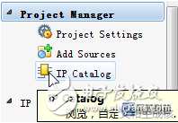
2. Select Multiplier under Math Functions, the multiplier, and double-click. 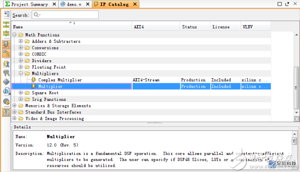
3. The IP core's parameter setting dialog box will pop up. Click Documentation in the upper left corner to open the manual for this IP core. Here, the input signals A and B are directly set to 4-bit unsigned data. Others are default values. Click OK. 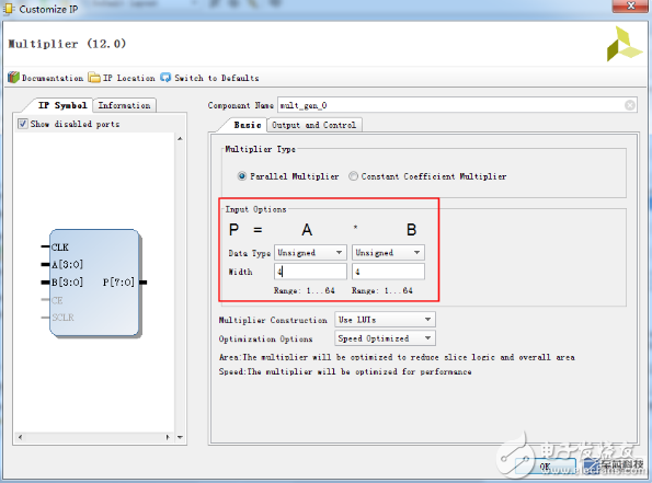
4. In the window that will pop up later, click Generate. 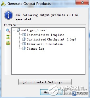
Second, call IP core
1. Select IP Sources, expand and select mult_gen_0 - Instantiation Template - mult_gen_0.veo to open the instantiation template file. As the figure shows, this code is the sample code that uses Verilog to call this IP core. 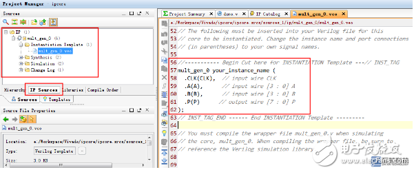
2. Copy the sample code into the demo.v file and modify it, as follows. The code declares the unsigned 4-bit variables a and b, and assigns the initial value of 7,8 to the multiplier, respectively; the unsigned 8-bit variable p stores the calculation result. Clk writes a 20ns cycle clock for Testbench; the mult_gen_0 mul(...) statement instantiates the module object mul of type mult_gen_0 and passes clk, a, b, and p as arguments. 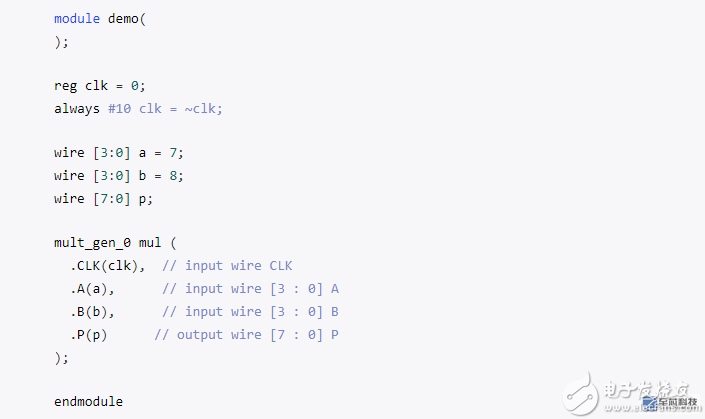
Third, behavior simulation verification
With the demo as the top module, start the behavior simulation and output the waveform. Set a, b, p as unsigned decimal (Right click Radix - Unsigned Decimal). As can be seen, a=7, b=8, p = a * b = 56 after the rising edge of the first clock.


Call IP Block in Block Design
Here is a simple example, by calling the multiplier IP core to generate a new module that can calculate the square.
First, create a block diagram design file
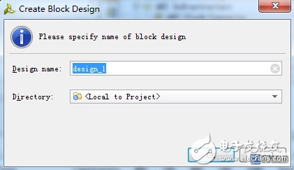
1. Select Create Block Design in Flow Navigator to create a block diagram design file.

2. Enter the file name and click OK.
Second, add IP core
1. Right-click in the blank area of ​​the diagram and select Add IP.
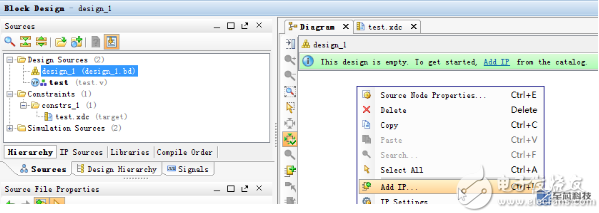
2. You can directly search for the required IP core and double-click to confirm.
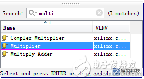
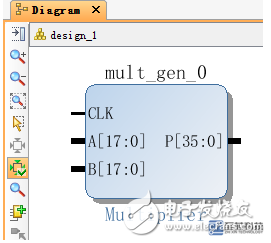
3. The IP core can be added and it can be connected to other devices with wires.
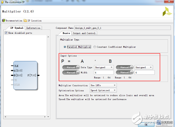
4. Double-click this IP core symbol to open the parameter setting dialog. Click Documentation at the top left to view the manual for the IP core. Here, input A and B are all set to 4 as unsigned type and others are default values. Click OK to confirm.
Third, draw the circuit
1. Right-click in the blank area of ​​the Diagram window and select Create Port.

2. In the popup window, set port a to a 4-digit input signal and click OK.
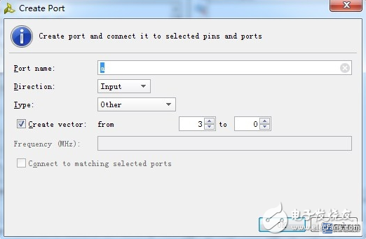
3. Connect a with A and B.
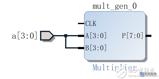
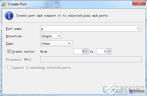
4. In the same way, add an 8-bit output port p to connect to P.
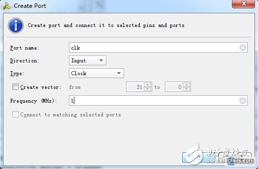
5. Add another clk clock input port to connect to CLK.
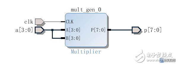
6. The final result is shown in the figure.
Fourth, the simulation test
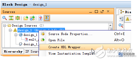
1. Right-click on the block diagram design file design_1 and select Create HDL Wrapper.
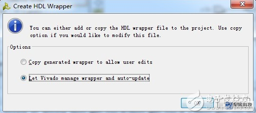
2. Select the second item and click OK.
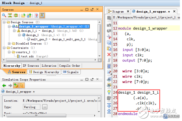
3. Open the generated design_1_wrapper.v file as shown in the figure, the code in the red box is used to call the Block Design module that was drawn earlier.
4. In the design_1_wrapper.v file, add the Testbench code to perform the behavior simulation. Modify the code as follows, to the input signal a initial value is 8, clk connected to the Testbench generated clock signal c.
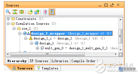
 5. In the Simulation Sources folder, set design_1_wrapper.v to the top level file for the behavior simulation (right-click and select Set as Top).
Start the behavior simulation and the final output waveform is as follows. It can be seen that after the first rising edge of clk, there is p = a*a = 64, that is, a squaring operation is implemented.
BIOTEPT NEMA EC Motor, Rolled Steel Frame, CSA&CUS Certified, EC Smart Motor, 48 Frame 1/4hp-1hp


Nema Ec Fan Motor,Ec Fan Motor,Nema Fan Motor,Ec Motor
Ningbo Biote Mechanical Electrical Co.,Ltd , https://www.biotept.com
