Impedance matching refers to an operating state in which the load impedance is matched with the internal impedance of the excitation source to obtain the maximum power output. For circuits with different characteristics, the matching conditions are different.
In a purely resistive circuit, when the load resistance is equal to the internal resistance of the excitation source, the output power is maximum. This operating state is called matching, otherwise it is called mismatch.
Why is impedance matching _ the importance of impedance matchingImpedance matching refers to a suitable match between the signal source or transmission line and the load. Impedance matching has two main functions, adjusting load power and suppressing signal reflection.
1, adjust the load power
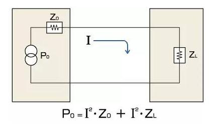
Assuming that the excitation source is fixed, the power of the load is determined by the impedance matching of the two. For an idealized pure resistance circuit or low frequency circuit, the reactance value caused by the inductor and capacitor is basically negligible. At this time, the impedance source of the circuit is mainly resistance. As shown in Figure 2, the current I = U / (r + R) in the circuit, the load power P = I * I * R. From the above two equations, P can obtain the maximum value when R=r, Pmax=U*U/(4*r).
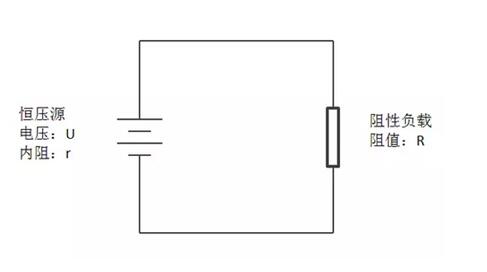
Figure 2 Load power adjustment
2, suppress signal reflection
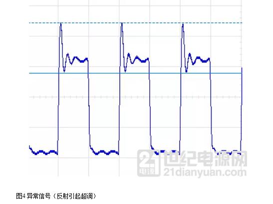
Reflection occurs when a beam of light is directed from the air into the water because of the different light guiding properties of light and water. Similarly, reflections can occur when a characteristic impedance change occurs on the transmission line during signal transmission. The wavelength is inversely proportional to the frequency. The wavelength of the low frequency signal is much larger than the length of the transmission line, so the reflection problem is generally not considered. In the high-frequency field, when the wavelength of the signal is the same as the length of the transmission line, the reflected signal is easily aliased with the original signal, affecting the signal quality. High-frequency signal reflection can be effectively reduced and eliminated by impedance matching.
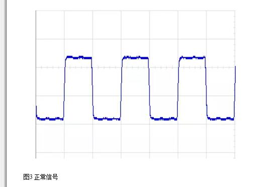
In a conventional wideband amplifier, since the output impedance is 50 Ω, it is necessary to consider impedance matching in the power transmission circuit. However, in practice, when the length of the cable is negligible for the wavelength of the signal, impedance matching is not required.
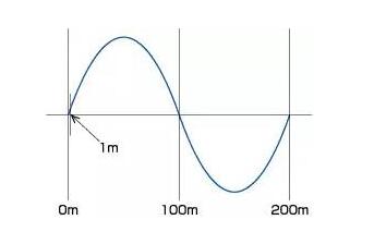
Consider a signal frequency of 1 MHz, a wavelength of 300 m in air and approximately 200 m in a coaxial cable. In the commonly used coaxial cable having a length of about 1 m, it is within a completely negligible range. (Figure H)
If there is an impedance, then power consumption will occur at the impedance, so without impedance matching, the output power of the amplifier will be wasted. (Figure J)
1. If it is an op amp, the input impedance is large, the bias current is small, the output impedance is small, and the load capacity is large.
2. Different circuit environments have different input and output impedance requirements. It is not simply stated by the size. For example, in the input circuit of the weak signal amplifying circuit, it is required that the larger the input resistance, the better, but in the power receiving conversion circuit, its input circuit is not like this, it is to show impedance matching. That is, try to call the input impedance equal to the output impedance of the front-end circuit!
The output impedance is not always as small as possible. Everyone knows that the output impedance of the output circuit that drives the speaker is also equal to the resistance of the speaker is the best!
Impedance matching methodThere are two main methods of impedance matching, one is to change the resistance of the group, and the other is to adjust the transmission line.
Changing the impedance is to adjust the load impedance value through series and parallel connection of capacitor, inductor and load to achieve source and load impedance matching.
Adjusting the transmission line is to lengthen the distance between the source and the load, and adjust the impedance to zero with the capacitance and inductance. At this point, the signal will not be emitted and the energy can be absorbed by the load. In high-speed PCB layout, the trace impedance of the digital signal is generally designed to be 50 ohms. The coaxial cable baseband is generally specified to be 50 ohms, with a frequency band of 75 ohms and a twisted pair (differential) of 85-100 ohms.
Impedance matching application1, amplifier and speaker
Whether it is a fixed impedance or a constant voltage output amplifier, the best working condition can be obtained only when the total power of the speaker and the total power of the power amplifier are equal. It is very difficult for the speaker system to fully match, and its audio components are always changing, but the speaker system does not require high impedance matching. The most common horn impedance is 8 ohms, which means that when a 1 kHz sine wave signal is input, it exhibits an impedance value of eight ohms; or within the operating frequency response range of the horn, the average impedance is 8 ohms.

Figure 5 speaker
2, PCB trace
In the high frequency field, the signal frequency has a great influence on the impedance value of the PCB trace. Generally speaking, the impedance problem should be considered when the edge time of the digital signal is less than 1 ns or the frequency of the analog signal exceeds 300 M. PCB trace impedance mainly comes from parasitic capacitance, resistance, and inductance. The main factors are material dielectric constant, line width, line thickness and even the thickness of the pad. PCB impedance ranges from 25 to 120 ohms, and USB, LVDS, HDMI, SATA, etc. typically require 85-100 ohm impedance control.
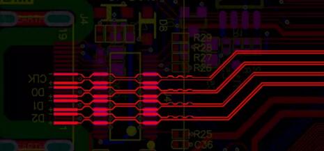
Figure 6 trace matching impedance
3, antenna design
The main purpose of studying antenna impedance is to achieve matching between the antenna and the feeder. The signal should be transmitted with the characteristic impedance of the transmitting antenna and the feeder equal to obtain the best signal gain. The antenna and the load should be conjugate matched when receiving the signal. The receiver (load) impedance is generally considered to have only the real part, so a matching network is needed to remove the reactance parts of the antenna and make their resistance parts equal. Figure 7 shows the commonly used π-type network for antenna impedance matching. The impedance is measured using a network analyzer to determine the values ​​of C1, C2, and C3 to complete impedance matching.
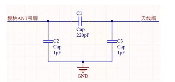
Figure 7 π-type circuit
4, terminal matching resistor
When designing the CAN bus and 485 bus, it is often necessary to add a terminating resistor (matching resistor) across the differential line to reduce signal reflection caused by a sudden change in the characteristic impedance. As shown in the following figure, the CAN bus network has a characteristic impedance of 120 ohms. If the terminal resistance is not directly suspended, the characteristic impedance of the air is infinite. At this time, the signal reflection shown in Fig. 4 is highly prone to occur.
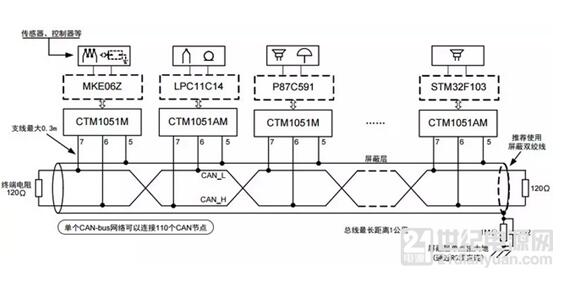
Figure 8 CAN bus network
For the CAN bus, since the position of the sampling point at which the transceiver determines the signal level is generally backward, the signal reflection generally does not affect the communication error rate. Reflection will affect the EMI characteristics of the product. The most direct performance is that the eye diagram experiment is poor, and there are two abnormal bumps.
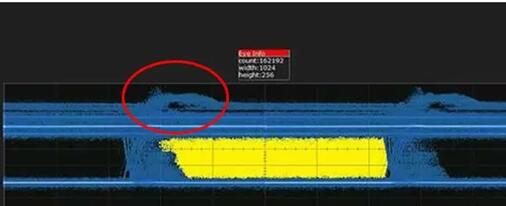
Figure 9 CAN bus eye diagram
Lcd Tonch Screen For Iphone,Lcd Display For Iphone,Lcd Touch Screen,Mobile Lcd For Iphone
Shenzhen Xiangying touch photoelectric co., ltd. , https://www.starstp.com
