The MC34063 itself contains a single-chip control circuit that is the primary function required by the DC/DC converter and is inexpensive. It consists of a reference voltage generator with automatic temperature compensation, a comparator, a duty-controlled oscillator, an RS flip-flop and a high-current output switching circuit. The device can be used in the control core of a boost converter, buck converter, and inverter. The DC/DC converter composed of it uses only a small number of external components. Mainly used in microprocessor-based (MPU) or microcontroller (MCU)-based systems.
Schematic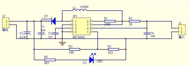
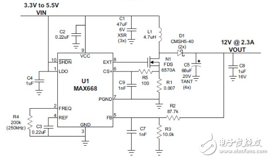
With the MAX668 integrated circuit, you can build a very simple and efficient power supply. With the MAX668, different power circuits can be designed to use very few external components. The power supply circuit based on the MAX668 integrated circuit is a high efficiency boost converter that will provide a fixed output regulation of approximately 12 volts with a maximum output current of 2.3 amps. This step converter circuit will provide an output voltage of 12 volts from 3.3 to 5.5 input voltage. As you can see in the table, the bellows, you can see the output voltage in harmony with the input voltage, from this circuit to detect the inductor R1 current The mode controller and some internally compared currents provide current limiting.
R5 triggers current limiting on the switching noise of the sense resistor with the C9 filter to prevent spurious. The MAX668's internal current limit threshold is fixed, changing resistor R1 and adjusting the current limit setting. Resistance, R2 set the operating frequency. The MAX668's external components can be rated for high voltages, providing greater flexibility in high-power applications.
Output 10A efficiency 90% input range 1.9~18V converter.
The LT1619 is not limited to low output voltage sources. It is also suitable for SLIC (User Line Interface Circuit) voltage generation, such as 5V to -48V conversion in telecom systems and SEPIC (single-ended primary inductor converter) conversion in automotive systems (input range 4V~28V).
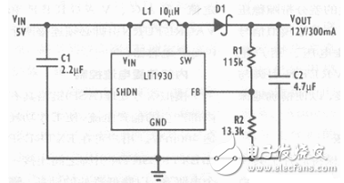
Figure 5 shows another typical application of the LT1930, a 5V to 12V boost converter. This circuit provides 300mA of output current with an efficiency of up to 87%. The maximum output voltage ripple of this circuit is 60mVp-p.
The LT1930 is the industry's highest power SOT-23 switching regulator. It can be used in SEPIC and flyback converter designs in addition to boost converters.
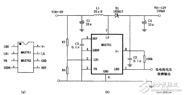
The figure shows a 5V → 12V boost supply consisting of the high efficiency, low power boost DC converter MAX761 and several peripheral components. Its characteristics are: conversion efficiency is 86%; quiescent current is 110μA; with low battery voltage detection function, R3, R4 are battery voltage detection voltage divider resistors, generally according to the empirical formula: R4=R3(VTPIP/1.5-1 ) to calculate, VTPIP is to detect the trigger voltage.
5v boost 12v circuit diagram (5)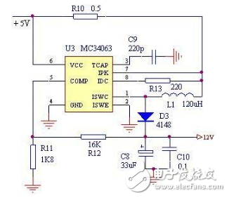
Using the LT3582-12 dual-channel DC-converting integrated circuit, linear technology production, can be designed in a very simple step up to DC converter.
This 5 to 12VC converter electronics project provides active applications such as OLED (Organic Light Emitting Diode) display as well as CCD (Charge Coupled Device) applications for active and negative outputs such as positive and negative output in many applications.
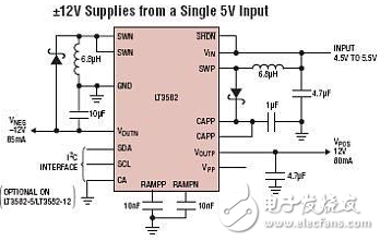
The LT3582 provides an I2C interface that can be used for dynamic application output voltage, power sequencing and output voltage ramping.
The positive output voltage of the LT3582 can be stepped between 3.2V and 12.775 in 25mV, while the negative output can be set between -1.2V and -13.95V50mV.
The LT3582-12 is a pre-set ±12V output and requires no future planning.
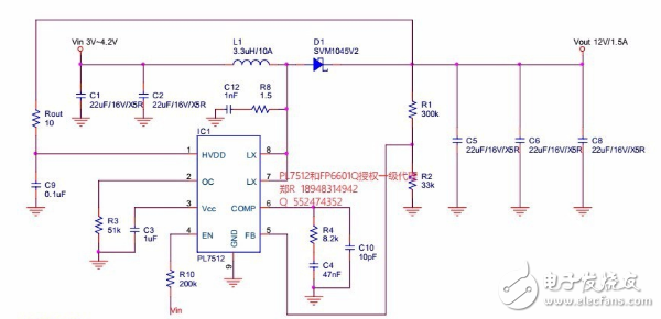
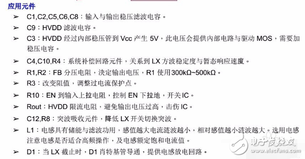
5V boost 12V circuit diagram. Output current up to 1.5A, adjustable overcurrent protection.
The following figure shows another typical application of the LT1930, a 5V to 12V boost converter. This circuit provides 300mA of output current with an efficiency of up to 87%. The maximum output voltage ripple of this circuit is 60mVp-p.
The LT1930 is the industry's highest power SOT-23 switching regulator. It can be used in SEPIC and flyback converter designs in addition to boost converters.
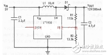
Features: 1.2MHz switching frequency (IT1930), 2.2MHz switching frequency (LT1930A), low VCESAT switch: 400mV at 1A current, high output voltage: up to 34V, 5V/480mA (LT1930) from 3.3V input, from 5V input for 12V/250mA (LT1930A), wide input range: 2.6V to 16V, small surface mount components, low power-down current: 1uA, flat profile (1mm) ThinSOT package, pin compatible with LT1613.
The LT1930 and LT1930A are the industry's highest power SOT-23 switching regulators. They all contain internal 1A, 36V switches, allowing for large current outputs on a small board footprint. The LT1930 switches at 1.2MHz, allowing the use of small, low cost and low capacitance capacitors and inductors. The faster LT1930A switches at 2.2MHz, which further reduces inductor size. With these devices, a complete regulator solution with an area close to one tenth of an inch can be made. Multiple output power supplies can now be used as separate regulators for each output supply, replacing the cumbersome quasi-adjustment method with a single regulator and custom transformer.
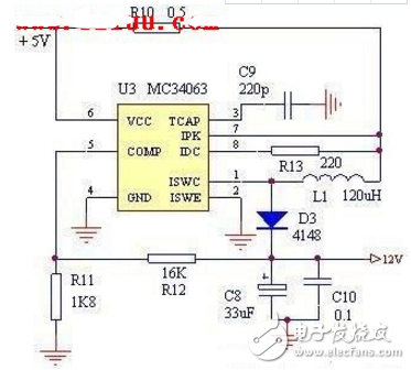
Introduction: It is known from the circuit that the input voltage is DC5V, which can be directly converted to DC12V output, which is suitable for some boosting applications. The logarithm of the components is shown in the figure, the components are few, the production is convenient, and the success rate is high.
5v boost 12v circuit diagram (10) 5 V boost to 30V DC / DC circuit diagram: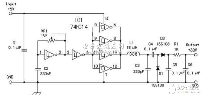
What is a Capsule Slip Ring?
Capsule slip rings are a type of electrical connector that are used to transfer power and data between two rotating objects. They are commonly used in applications where there is a need to send or receive signals from a stationary object to a rotating one, or vice versa.
How Does it Work?
Capsule slip rings work by using a series of electrical contacts that rotate with the object on which they are mounted. These contacts are spaced evenly around the circumference of the ring, and as they rotate they make and break contact with corresponding contacts on the other object. This allows power and data to be transferred between the two objects without any interruption.
Advantages of Capsule Slip Rings
There are several advantages to using capsule slip rings in place of other types of electrical connectors.
For example, the rotation of the contacts causes them to be freely accessible and therefore free from dust and debris. This makes them ideal for applications where connector maintenance is often a problem.
Because the contacts are freely accessible, they can be readily replaced if a fault occurs. They also have very low electrical resistance, making them ideal for transmitting radio frequency signals. Because of the low resistance, this type of connector is often used in high-speed data transmissions.
This type of Conductive Slip Ring is similar to the shape of a hat. The brim part is a flange with a conductive slip ring. The function of the flange is to facilitate installation. It is connected to electrical equipment through the fixing hole of the flange. It can be firmly installed on the equipment. Therefore, the stator of the cap-type slip ring is generally fixed by the outer layer with a flange, and the inner part is the rotor with the inner shaft rotating. The stator and the rotor are not fixed, and the details will be different according to the installation method.
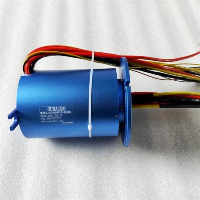
Capsule Slip Ring,Split Ring Motor,Slip Ring Motor Connection,Slip Rings In Synchronous Motor
Dongguan Oubaibo Technology Co., Ltd. , https://www.sliprob.com
