Although rail-to-rail single-supply op amps are widely used, it is often necessary to generate two supply rails (for example, ±15 V) from a single (positive) input rail to power different parts of the analog signal chain. The current in these sections is typically low (eg 10 mA to 500 mA) and the positive and negative supplies have relatively well matched loads.
One solution to this problem is to use two different converters, one to provide a positive supply rail and one to provide a negative supply rail. This is costly and, as shown in this application note, is not necessary. Another solution is to use a flyback converter. However, the two power supplies often do not agree very well under differential loads, require large and expensive transformers, and are inefficient.
A better solution is to use a SEPIC-C'uk converter consisting of an output unregulated C'uk converter connected to the same switching node and an output regulated SEPIC converter. The two power supplies produced by this combination are very consistently consistent under all conditions unless the load is 100% mismatched.
The working principle of the converter and the implementation of the ADI ADP161x are analyzed to prove that the topology is comprehensive. In addition, this article introduces a revolutionary new design tool that helps to quickly implement the SEPIC-C'uk converter in user applications.
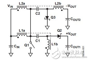
Figure 1. Schematic of the SEPIC-C'uk converter
Topology descriptionAt first glance, the SEPIC-C'uk seems to be a very complex converter with four different inductors and switches. However, it can be thought of as consisting of two converters to simplify the analysis. For SEPIC or C'uk converters, the Q1 and Q2 switches operate in opposite phases. Figure 2 shows the current flow of the SEPIC converter in two different switching states.
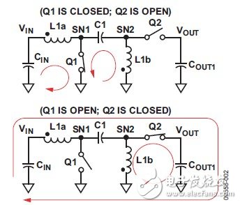
Figure 2. Current flow of the SEPIC converter
Although not very obvious, the voltage of the transfer capacitor (C1) is approximately constant VIN (with very small ripple).
Figure 4 shows the ideal waveform for a SEPIC converter. When Q1 is turned on, the voltage of SN2 is equal to -VIN. Therefore, during Q1 turn-on (Q2 open), the voltage on L1a and L1b is VIN; when Q1 is off (Q2 is on), L1a and L1b are on The voltage is -VOUT. Applying the volt-second balance principle of the inductor, the steady-state DC conversion ratio can be calculated as shown in Equation 1. D is the duty cycle of the converter (the proportion of Q1 on-time in the switching cycle).
The C'uk converter works like a SEPIC converter, but switch Q2 is grounded instead of connected to the output, and inductor L2b is connected to the output instead of ground. Figure 3 shows the current flow of the C'uk converter at both switch positions.
C'uk is a negative output converter, so the current flowing out of the load supplies it with energy.
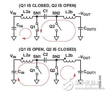
Figure 3. Current flow of the C'uk converter
The ideal waveform of the C'uk converter is shown in Figure 4. Applying the principle of inductor volt-second balance and capacitor charge balance, the voltage on C1 is VIN + VOUT. Therefore, the SN2 switch node switches between GND (when Q2 is closed) and - (VIN + VOUT). When Q1 is turned on (Q2 is off), the voltage on L2a and L2b is VIN; when Q1 is off (Q2 is on), the voltage on L2a and L2b is -VOUT.
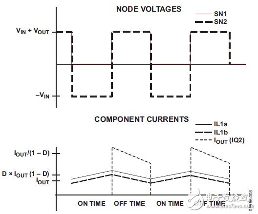
Figure 4. SEPIC ideal waveform comparison
As can be seen from the waveforms in Figures 4 and 5, the voltage across the inductor in C'uk is exactly the same as in SEPIC. Therefore, the duty cycle relationship of C'uk is exactly the negative value of SEPIC, as shown in Equation 2.
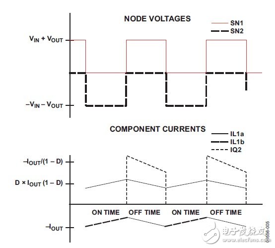
Figure 5. C'uk ideal waveform
Since the duty cycle relationship is equal in magnitude but opposite in sign, the switching node (SN1) has the same voltage and the same inductor current, so the two converters can be simply connected to the node SN1 at the same time. The combined converter is shown in Figure 1. .
Q2 and Q3 are replaced by diodes because these power supplies are typically low power analog power supplies and are suitable for use with asynchronous controllers. In addition, the two inductors (L1a and L2a) are connected in parallel because L1a and L1b, L2a and L2b are coupled together by two independent coupled inductors, which brings several benefits.
The coupled inductor reduces the current ripple in the inductor by a factor of two (see the C'uk-Middlebrook paper cited in the "References" section). In addition, it eliminates the SEPIC and C'uk resonances determined by Equations 3 and 4, significantly reducing the complexity of the small-signal model and supporting higher bandwidths. In this way, we can use a wide variety of off-the-shelf devices without being limited to a few three-winding 1:1:1 inductors.

Six-winding devices such as the Coilcraft Hexapath series or custom three-winding transformers can also be used.
Coupling coefficient limitation
Shockproof Armor Phone Case For IPhone
Shockproof Armor Phone Case For Iphone,Shockproof Armor Phone Case,Shockproof Armor Iphone Case,Best Shockproof Armor Phone Case
Guangzhou Jiaqi International Trade Co., Ltd , https://www.make-case.com
