
CCD (Charge Coupled Device) is made of a high-sensitivity semiconductor material that converts light into electric charge, which is converted into a digital signal by an analog-to-digital converter chip. The digital signal is compressed by the internal flash memory of the camera. Or the built-in hard disk card can be saved, so that the data can be easily transferred to the computer, and the image can be modified according to needs and imagination by means of computer processing. The CCD consists of many photosensitive units. When the CCD surface is exposed to light, each photosensitive unit reflects the charge on the component. The signals generated by all the photosensitive units are added together to form a complete picture. It is like the photoreceptor system of the traditional camera's negative film. It is a circuit device that senses light. You can think of it as tiny tiny sensor particles, which are covered behind the optical lens. When the light and the image are transmitted from the lens to the lens. On the CCD surface, the CCD generates a current, which converts the sensed content into digital data for storage. The more the number of CCD pixels and the larger the single pixel size, the clearer the collected image will be. Therefore, although the number of CCDs is not the only focus on determining image quality, we can still consider it as one of the important criteria for camera level. At present, most scanners, camcorders, and digital cameras are equipped with CCDs.
After 35 years of development, the CCD has been shaped and shaped. The composition of the CCD is mainly composed of a mosaic-like grid, a concentrating lens, and a matrix of electronic circuits under the bottom. The companies that currently have the ability to produce CCDs are: SONY, Philps, Kodak, Matsushita, Fuji, and Sharp, most of which are Japanese manufacturers.
CMOS (Complementary et al-Oxide Semiconductor, an additional metal oxide semiconductor device) is the same as a CCD, which is a semiconductor that can record light changes in a digital camera. CMOS manufacturing technology is no different from general computer chips, mainly using semiconductors made of two elements, silicon and germanium, to coexist with N (band-to-electric) and P (with +-electric) levels in CMOS. The semiconductor, the current generated by these two complementary effects can be recorded and interpreted by the processing chip into an image. However, the shortcoming of CMOS is that it is too easy to appear noise, mainly because the early design makes CMOS overheat when the current changes too frequently when dealing with fast-changing images.
The advantages and disadvantages of CCD and CMOS, we can compare the main differences between the two from a technical point of view:
The information is read in different ways. The charge information stored by the CCD sensor needs to be read one bit after the transfer of the synchronous signal control. The charge information transfer and the read output need to have a clock control circuit and three different sets of power supplies. The whole circuit is complicated. The CMOS sensor directly generates a current (or voltage) signal after photoelectric conversion, and the signal reading is very simple.
The speed is different. The CCD sensor needs to output one bit of output information under the control of the synchronous clock, and the speed is slow. The CMOS sensor can extract the electrical signal while collecting the optical signal, and can simultaneously process the image information of each unit. A lot faster than CCD.
Power and power consumption. CCD sensor charge couplers mostly need three sets of power supply, which consumes a lot of power; CMOS sensor only needs one power supply, and the power consumption is very small, only 1/8 to 1/10 of CCD charge coupler, CMOS photoelectric sensor It has great advantages in energy saving.
Imaging quality. The CCD sensor fabrication technology started earlier and the technology is relatively mature. The PN combined with the silicon dioxide isolation layer is used to isolate noise, and the imaging quality has certain advantages over the CMOS sensor. Due to the high integration of the CMOS sensor, the distance between the photoelectric sensor element and the circuit is very close, and the optical, electrical and magnetic interference between each other is serious, and the noise has a great influence on the image quality. At the same resolution, CMOS is cheaper than CCD, but the quality of the image produced by CMOS devices is lower than that of CCD. So far, the vast majority of consumer grades and high-end digital cameras on the market use CCDs as sensors; CMOS sensors are used as low-end products on some cameras. Whether or not there is a CCD sensor has once become one of the standards for people to judge the grade of digital cameras. Since CMOS's manufacturing cost and power consumption are lower than CCD, many mobile phone manufacturers use CMOS lenses. Nowadays, most mobile phones on the market use CMOS cameras, and a few also use CCD cameras.
Optical zoom and digital zoom principleOptical Zoom (OpticalZoom) is produced by changing the position of the lens, object and focus. When the image plane moves in the horizontal direction, as shown below, the vision and focal length will change, and the farther scene becomes clearer, making people feel like the object is moving forward.
Obviously, there are two ways to change the angle of view. One is to change the focal length of the lens. In the case of photography, this is the optical zoom. The focal length of the lens is changed by changing the relative positions of the lenses in the zoom lens. The other is to change the size of the imaging surface, that is, the diagonal length of the imaging surface. In the current digital photography, this is called digital zoom. In fact, the digital zoom does not change the focal length of the lens, but changes the angle of view by changing the angle of the image facing the corner, resulting in the effect of "equivalent" lens focal length change.
So we see that some digital cameras with longer lenses have larger internal lens and photoreceptor movements, so the zoom factor is also larger. We see some ultra-thin digital cameras on the market, generally do not have optical zoom function, because the root of the fuselage does not allow the movement of the photosensitive device, and the "long lens" digital camera like Sony F828, Fuji S7000, optical zoom The function reaches 5 or 6 times.
Digital Zoom (Digital Zoom) is also called digital zoom. Digital zoom is achieved by a processor in a digital camera that increases the area of ​​each pixel in the image to achieve magnification. This method is like using image processing software to change the area of ​​the image, but the program is carried out in the digital camera, and some pixels on the original image sensor are amplified by using the "interpolation" processing method, and the pixels on the image sensor are used. Use the interpolation algorithm to enlarge the picture to the entire picture.
Unlike optical zoom, digital zoom is a vertical change in the vertical direction of the sensor, giving it a zoom effect. The smaller the area on the photosensitive device, the visually let the user see only the part of the scene. However, since the focal length does not change, the image quality is poor relative to the normal case.
With digital zoom, the subject is magnified, but its sharpness will drop to a certain extent, so digital zoom does not have much practical significance. Because too much digital zoom can seriously damage the image, and sometimes even because the magnification is too high, you can't tell the picture you are shooting.
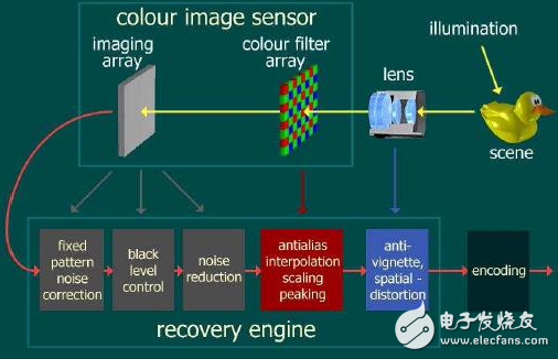
How the Sensor works internallyAfter the external light passes through the lens, it is filtered by the colorfilter and then irradiated onto the Sensor surface. The Sensor converts the light transmitted from the lens into an electrical signal, and then converts it into a digital signal through the internal DA. If the Sensor does not have an integrated DSP, it is transmitted to the baseband through DVP. The data format at this time is RAWRGB.
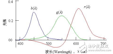
The recognition of color by the human eye is based on the fact that the human eye has three different sensing units for the light, and different sensing units have different response curves for different wavelengths of light, and the color perception is obtained through the synthesis of the brain. In general, we can use the concept of RGB three primary colors to understand the decomposition and synthesis of colors.
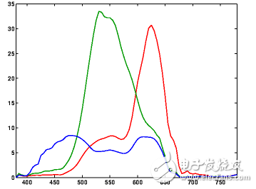
In theory, if the response of the human eye and the sensor to the color light of the spectrum is as follows in the spectrum, basically, the response to the three-color light does not affect each other, and there is no so-called cross effect.
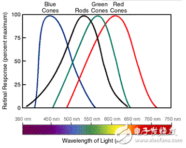
However, the actual situation is not so ideal. The figure below shows the response of the human eye's three-color sensing system to the spectrum. It can be seen that the response of RGB is not completely independent.
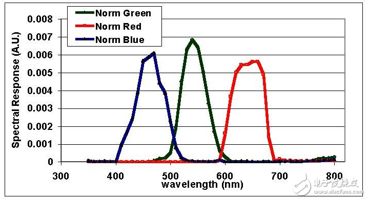
The figure below shows the response of a Kodak camera spectrum. It can be seen that there is a big difference between the response curve and the human eye.
Since we have already seen the response of the sensor to the spectrum, the response to the spectrum of the human eye on the RGB components is usually biased, and of course it needs to be corrected. Not only in the cross-effect, but also the intensity of the response to the various components of the color needs to be corrected. The usual practice is to correct the color once by a color correction matrix.
The color correction operation is usually done by the sensor module integration or the back end ISP, and the software corrects the result by modifying the relevant registers. It is worth noting that since the conversion of RGB - "YUV" is also realized by a 3*3 transformation matrix, sometimes these two matrices are merged together during the ISP processing, and completed by a matrix operation. Color correction and color space conversion.
2, color space 2.1, classificationIn fact, the description of the color is very complicated. For example, the RGB three-primary color adding system cannot cover all possible colors. For various color expressions, as well as color conversion and hardware and software applications, there are various color models. And the expression of the color space. These color models can be divided into different categories according to different principles according to different classification criteria.
The three primary color light ratio curves required to match any visible light
For sensor, the concept of color space that we often touch, mainly RGB, YUV (in fact, these two systems contain many different color expressions and models, such as sRGB, Adobe RGB, YUV422 , YUV420 ...), RGB as described above is to describe the color according to the principle of the three primary color lighting system, and YUV is to describe the color according to the principle of brightness and color difference.
2.1.1 RGB "-" YUV conversion
There is no standard conversion formula for conversions other than color space. Because YUV is largely hardware-dependent, the conversion formulas for RGB and YUV are usually different versions, slightly different.
The common formula is as follows:
Y=0.30R+0.59G+0.11B
U=0.493(B-Y) = -0.15R-0.29G+0.44B
V=0.877(R-Y) = 0.62R-0.52G-0.10B
However, the YUV value obtained in this way has a negative value and the difference between the upper and lower limits of the value range is not 255, etc., which is not conducive to computer processing. Therefore, according to different understandings and requirements, various different methods are usually used in software processing. The formula for deformation is not listed here.
Reflected on the Sensor, we will also find that some Sensors can set the YUV output range. The reason is this.
From the formula, our key point to understand is that the UV signal is actually the blue difference signal and the red difference signal. In other words, in fact, it indirectly represents the intensity of blue and red to some extent. Understanding this for us Understanding the process of various color transformations can be very helpful.
3.1, white balance 3.1.1, color temperatureThe definition of color temperature: the black body is heated from absolute zero. The temperature is raised by one degree Celsius (indicated by the letter K). When the temperature rises to a certain extent, the black body radiates visible light, and its spectral composition And the feeling of giving people will change accordingly with the rising temperature. Thus, the temperature at which the black body radiates a certain color of light is set as the color temperature at which the light source of the same color light is emitted.

Light source color temperature (K)
Tungsten lamp (incandescent lamp) 2500-3200k
Carbon rod light 4000-5500k
Fluorescent lamp (fluorescent lamp, energy saving lamp) 4500-6500k
Xenon lamp 5600 k
Carbon lamp 5500~6500k
Daylight average 5400k
Daylight 6500-7000k under cloud weather
Cloudy daylight 12000-18000k
As the color temperature increases, the color of the light source transitions from warm to cool, and the energy distribution in the light source is also shifted from the red end to the blue end.
It is worth noting that the spectral distribution of the actual light source is different, and the color temperature only represents the degree of weight of the energy, and does not reflect the specific spectral distribution, so even a light source of the same color temperature may cause different color reactions.
The human eye and the brain have certain physiological and psychological adaptability to the color temperature, so the color seen is less affected by the color temperature shift, and the camera sersor does not have this ability, so the photographs taken are not subjected to white balance processing. If there is a large deviation from the color seen by the human eye (although the true color of the human eye is also deviated from the white light).
The color temperature of the sun varies with the weather and time, and is related to the refractive index of light at different frequencies:
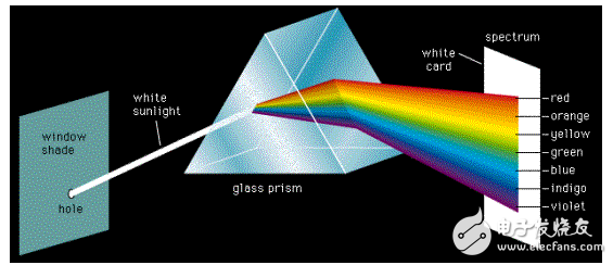
Long wavelength light, low refractive index, strong transmission, short wavelength light, large refractive index, easy to be scattered, low refractive index, which is why traffic lights are red, anti-fog lights are usually yellow, why the sky is blue The reason for the color and so on.
Knowing this, the laws and causes of the change in the color temperature of the sun can be understood and analyzed, leaving everyone to think for themselves.
3.1.1 Color correction when color temperature changes
Therefore, it can be seen from the theory that as the color temperature increases, the color temperature should be corrected. Otherwise, the color of the object under such light conditions will deviate from its normal color, so it is necessary to reduce the sensor to red. The gain increases the gain of the sersor to the blue light. At the same time, when adjusting the parameters, it must be considered that the overall brightness should remain roughly the same, that is, when measured by YUV, the Y value should remain basically unchanged. Theoretically, it can be considered that RGB-"YUV transformation formula, RGB The contribution of the three components to the Y value determines the proportional relationship between the changes in RGAIN and BGAIN. However, the actual situation is more complicated than this. Considering the cross-effect and nonlinearity of the sensitivity of different sensors to R and B, the optimal value may have some deviation from the theoretical value.
3.1.2 Principle of automatic white balance
3.1.2.1 Principle
The automatic white balance is based on the assumption that the average value of the color of the scene falls within a specific range. If the measured result deviates from the range, the corresponding parameter is adjusted and corrected until its mean falls within the specified range. This process may be based on the YUV space or on the RGB space. For the Sensor, the usual way to do this is by correcting the R/B gain so that the UV value falls within a specified range. Thereby achieving automatic white balance.
3.1.2.2 Treatment of special cases
In the automatic white balance, the problem that is easy to encounter is that if the scene is shot, the effect of the color temperature of the light is excluded, and the color of the light itself deviates from the average color value, such as a large area of ​​a pattern that is biased toward a certain color such as grass, red flag, Blue sky, etc. At this time, the forced white balance will adjust its average color to the vicinity of the gray, and the image color will be seriously distorted.
Therefore, the usual practice is to set the color range 一对 value of a pair of source images in addition to the expected color range of the target result when processing the automatic white balance, if the unprocessed image has a color average value exceeding the If you depreciate, you will not do automatic white balance processing at all. This ensures the correct handling of the above special circumstances.
It can be seen that the determination of these two pairs of enthalpies plays a key role in the effect of automatic white balance.
3.1.3 Examples of a platform
English code Chinese interface color temperature color temperature RGAIN, GGAIN, BGAIN
Cloud cloudy 7500k 0x1D4C, 0x00CD, 0x0085, 0x0080
Daylight Daylight 6500k 0x1964, 0x00A3, 0x0080, 0x0088
INCANDESCENCE White Hot Light 5000k 0x1388, 0x00A5, 0x0080, 0x0088
FLUORESCENT fluorescent lamp 4400k 0x1130, 0x0098, 0x0080, 0x00A8
TUNGSTEN Tungsten Light 2800k 0x0AF0, 0x0080, 0x0081, 0x00A4
It can be seen that as the color temperature increases, the law of change basically conforms to the theoretical analysis in the previous section. However, most of the parameters here have some deviations from the theoretical values. The color temperature parameter setting of the fluorescent lamp has a large deviation from the theoretical value. The actual effect also proves that the parameter setting of the fluorescent lamp makes the color of the photograph taken in the home fluorescent environment blue. After the parameters were modified, the real shot effect was significantly improved. (After checking some information, you can see that there are usually two kinds of fluorescent lamps with color temperatures of 4000 and 5000K. At present, I should be exposed to 5000K.)
3.1.4 Debugging and verification
The adjustment of specific parameters should be carried out in a light box environment using a standard light source of various known color temperatures for the standard color card. The color deviation on the RGB component of the standard swatch is measured by the color picking tool on the Pc machine. Adjust the proportional relationship of each component gain. In order to get more accurate results, the exposure gain setting should be corrected relatively accurately before this.
4, color-related effects processing 4.1 grayscale (grayscale)The effect of a grayscale image is to convert a color image into a black and white image.
4.2 TheoryIn theory, in the YUV space, the UV component is discarded, and only the Y component is retained, so that a black and white image can be obtained, which is also the principle that the color electric machine signal can be compatible with the black and white television. The following figure theoretically has the same Y value (the effect of converting to a grayscale image with acdsee), which should be the same color in grayscale mode.

In the operation of the algorithm, it is theoretically possible to change the UV value to a gray corresponding value. However, depending on the software algorithm and hardware structure, the specific code will be different.
4.3 Taking a platform as an exampleThe two lines of the core code are as follows:
SET_HUE_U_GAIN(0);
SET_HUE_V_GAIN(0);
Here, the UV GAIN is set to 0. If the UV offset is set to 128, the resulting UV is 128, which is consistent with the theory.
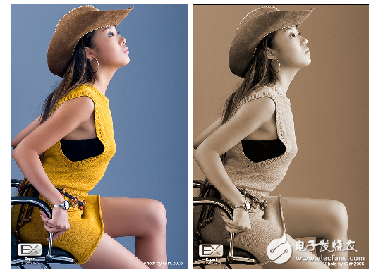
4.4 sepia / sepiagreen / sepiablueThe so-called retro (green, blue) is based on the gray level, an additional offset to the UV value, the gray map is converted into a gradient map of a certain color. In theory, in order to obtain a blue effect, the blue difference signal should be increased to reduce the red difference signal. That is, increase U and decrease V.
Taking the sepiablue effect as an example, the MSB of the byte here represents the sign bit: so 88 is 88 and 158 is -30.
SET_HUE_U_GAIN(0);
SET_HUE_V_GAIN(0);
SET_HUE_U_OFFSET(88);
SET_HUE_V_OFFSET(158);
The so-called negative effect is to reverse the color of the image, which looks like the effect when looking at the film negative. This is also very easy to understand and deal with in theory, that is, in the RGB space, take its complementary color, the specific operation is to subtract RGB from 255 to get the new RGB value. This feature is usually implemented in the ISP.

Liquid Crystal Display,Lcd Screen Displays,Calculator Lcd Display,Lcd Display For Car Bluetooth
Dongguan Yijia Optoelectronics Co., Ltd. , https://www.everbestlcdlcm.com