The improvement of CAN transceiver and the introduction of isolation device greatly improve the reliability of communication, but also introduce additional delay, resulting in shorter communication distance or bus error frame. This paper uses 1Mbps baud rate as the application. For example, a brief analysis of the CAN bus signal delay.
Related factors of CAN bus transmission distance
1, ACK response
The CAN bus uses a multi-master communication mode and a non-destructive bus arbitration mechanism. Taking the standard number frame as an example, it is divided into 7 segments from the structure, which are the start segment, the arbitration segment, the control segment, the number segment, the CRC check segment, the ACK response segment, and the frame end segment, as shown in Figure 1. :
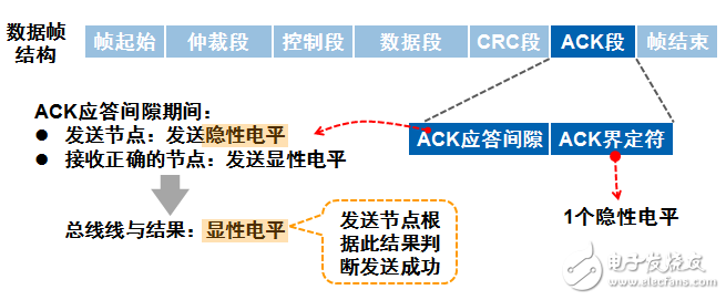
Figure 1 Standard number frame structure and response
The ACK segment is 2 bits long and contains the acknowledgement gap (ACK SLOT) and the response delimiter (ACK DELIMITER). In the answer field, the transmitting station sends two "recessive" bits. When the receiver correctly receives a valid message, the receiver sends a "dominant" bit to the transmitter during the acknowledgment gap (ACK SLOT) to acknowledge. When the transmitting node detects that the bus is in an explicit state, it considers that a node has responded effectively and the frame it sent is normal.
2, CAN bus bit time composition
CAN network communication bit timing parameters are shown in Figure 2.
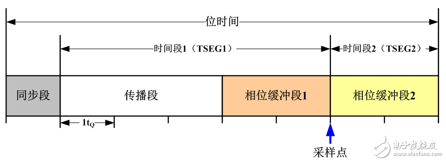
Figure 2 Bit timing diagram
The time of each bit in the CAN bus communication consists of four parts, namely, the sync segment, the propagation segment, the phase buffer segment 1, and the phase buffer segment 2, which are divided into three segments.
Synchronization segment: used for synchronization between nodes of the bus;
Time period 1: consists of a propagation segment and a phase segment 1 for compensating for the physical propagation delay of the signal;
Time period 2: phase buffer segment 2, phase segment 1 and phase segment 2 are used to compensate the phase error of the edge.
In the actual controller design, the compensation time for the bus propagation delay can be changed by adjusting the values ​​of time period 1 and time period 2.
3. Theoretical analysis of CAN bus delay
It can be seen from Figure 1 that after the CRC field is sent, the transmitting node will send a response slot. During this time, the receiving node should output an explicit bit as a response. If the sending node does not detect valid in the response slot. The explicit bit determines the bus error, so the fundamental condition for limiting the upper limit of the signal propagation delay of the CAN bus system is to ensure that the transmitting node receives a valid acknowledge signal in the response slot.
In order to meet this fundamental condition, the single-point sampling mode is taken as an example at a baud rate of 1 Mbit/s, and is set to a 75% bit width according to the sampling point before and after the setting of the synchronization segment, the time segment 1, and the time period 2. Time (ie, the sampling point is located at 75% of the width of the start of the distance, 750 ns), in the response gap to enable the transmitting node to acquire a valid explicit bit, theoretically, the entire signal propagation delay must be less than 750 ns . That is, the total delay of the isolation device, bus driver, cable, etc. is less than 750 ns to ensure the response is valid. As shown in Figure 3:
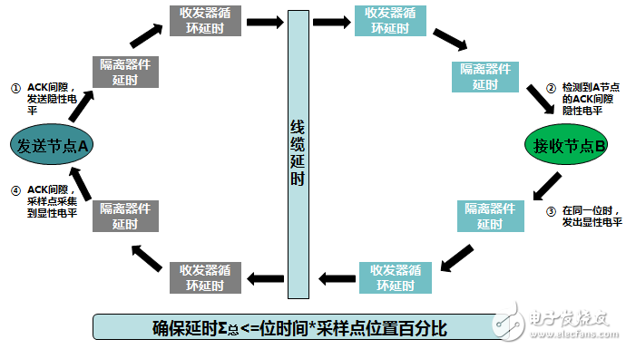
Figure 3 CAN bus delay theory analysis block diagram
CAN bus delay analysisFirst, we look at the propagation delay of the communication between nodes on the CAN network, as shown in Figure 4, t2, t5 is the transceiver cycle delay, t3, t6 is the isolation delay, t4, t7 is the CAN controller processing delay When t1 is the cable transmission delay.
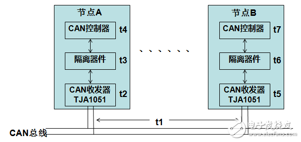
Figure 4 CAN bus signal transmission delay
Sended by node A, node B receives as an example. From the start of CAN message transmission to the receipt of ACK response, the delay of the whole response loop is T total = (t1 + t2 + t3 + t4 + t5 + t6 + t7) * 2 During the period, the message has passed 4 isolations and transceivers, and two cables. If you want to increase the transmission distance, you need to analyze the delay time of each link.
1, isolation device delay
In order to improve the reliability of the CAN node, the CAN underlying hardware usually uses an isolation design. Commonly used solutions use optocoupler + CAN transceiver, as shown in Figure 5 (6N137 + TJA1051), optocoupler 6N137 has a typical 60ns one-way delay, and all bidirectional signals must pass 4 optocouplers, total isolation delay Up to 240ns, the allowable cable length of the CAN system is greatly shortened with the same time configuration.
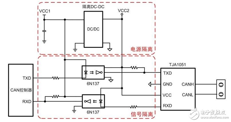
Figure 5 optocoupler isolation delay

Figure 6 Isolated transceiver delay
Or use the isolated transceiver scheme as shown in Figure 6. The CTM1051KT uses magnetic coupling isolation. The magnetic isolation delay is 3~5ns. When the bit time configuration is unchanged, the CTM1051KT self-contained isolation will not affect the allowable cable length. A transmission distance of about 36 m at a rate of 1 Mbps is satisfied.
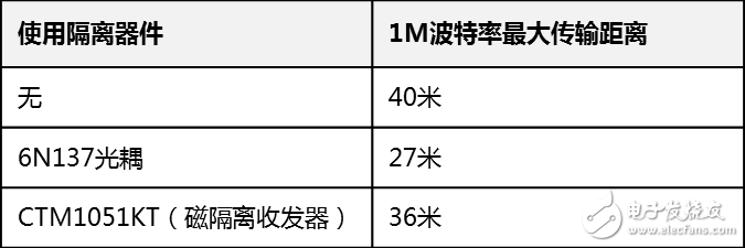
Figure 7 Different isolation device delays
2, transceiver cycle delay
What is a loop delay? For a CAN transceiver, the digital stream input from the TXD is converted to a corresponding analog bus signal, while the bus transceiver monitors the bus and converts the analog bus signal into a corresponding digital bit stream for output from the RXD. As shown in Figure 8:
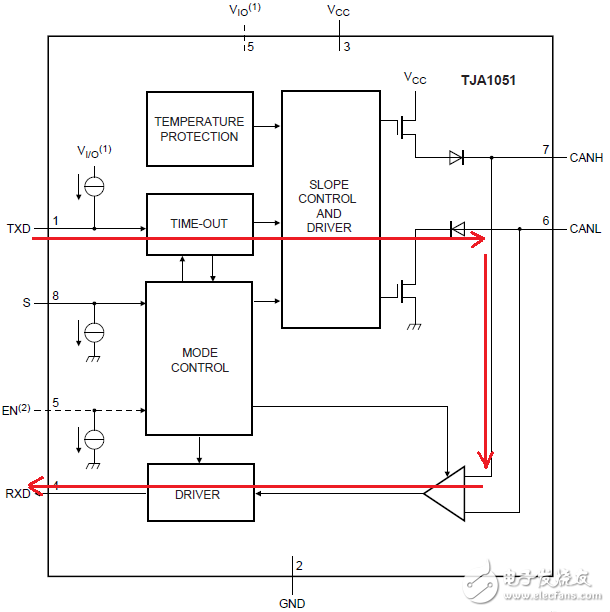
Figure 8 TJA1051 functional block diagram
Manufacturers of CAN transceivers typically specify a "cycle delay" that includes driver and receiver delays. The delay time is determined by the characteristics of the transceiver itself. Take the transceiver TJA1051 as an example. As can be seen from the data sheet, the maximum propagation delay is 220 ns and the minimum propagation delay is 40 ns. Figure 9 is a symmetrical timing diagram of the transceiver cyclic delay (tPD (TXD-RXD) is the delay for TXD to send a dominant rising/falling edge to the bus and fed back to RXD). The transceiver cyclic delay is mandatory for the CAN bus specification. Projects, select higher performance transceivers, can reduce transmission delay, and help increase transmission distance.
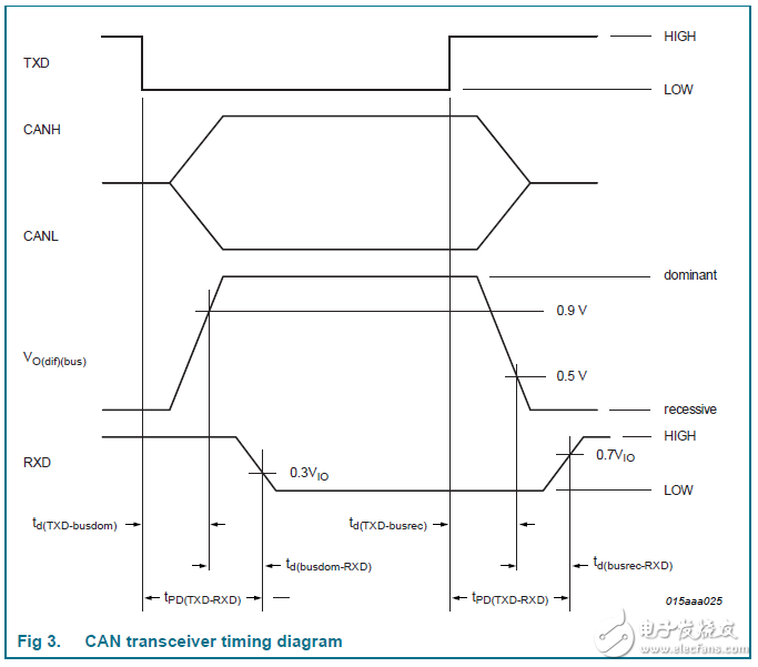
Figure 9 loop delay symmetrical timing diagram
3, CAN controller delay
Software delay: It is the time taken by the main CPU to read/write data from the CAN controller and perform preliminary processing in the application process.
CAN controller delay: It is the overhead time for the CAN controller to realize the mutual conversion of the information in the receive/transmit buffer and the serialized information.
The delays caused by software and controllers are related to the specific application, master, CAN controller and interface chip. Considering that the bus controller has been designed with internal processing time in mind, the delay should be below the nanosecond level, which can be ignored here.
4, cable propagation delay
The cable selection is different, the delay rate is also different, and the transmission distance will have a greater impact. How to calculate the communication length of the cable in the case of the CAN controller, transceiver, isolation and other peripheral components? ?
If the communication distance of the cable is L (in m), the communication rate is B (in bit/s), the sampling position is P (such as 75%), and the isolation device propagation delay is tg (in ns) For example, t3, t6), the transceiver propagation delay is tq (in ns, such as t2, t5), and the cable propagation delay is tx (in ns/m).
An estimate of the cable communication length can be obtained: L=[(1/B)•P–4(tg+tq)]/2tx
It can be known from the formula that the smaller the cable delay rate is, the farther the transmission distance is under the same conditions. Therefore, in cable selection, it is recommended to use thicker wires (the larger the wire diameter, the smaller the delay), or Gold-plated or silver-plated cable.
In practical applications, how to quickly evaluate the delay of CAN network? Using the electronic CANscope for bus delay analysis, the test results are shown in Figure 10:
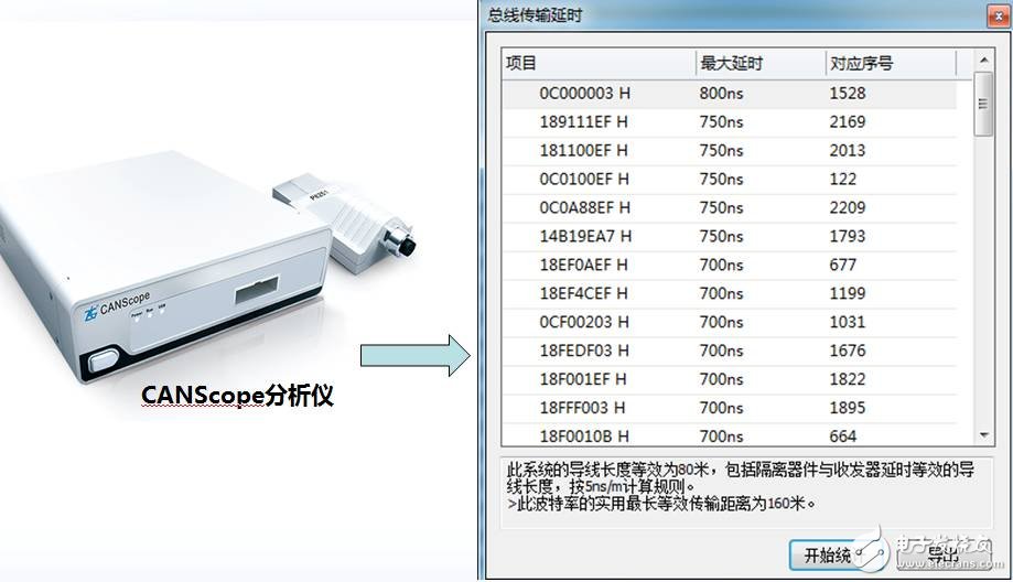
Figure 10 CAN bus transmission delay analysis
to sum upThe introduction of peripheral circuits such as isolation devices and the addition of long-term dominant shutdown functions to the transceivers have increased the delay time of the CAN bus, resulting in newer transceivers, increased loopback delay, and reduced actual communication distance. If you want to increase the communication distance of CAN bus, you must understand the principle of CAN communication and the principle of signal line transmission. By improving the performance of transceivers, isolation devices and cable selection, the delay time of CAN signal transmission can be reduced, thereby improving The distance of actual communication.
1000 puffs disposable vape pen are so convenient, portable, and small volume, you just need to take them
out of your pocket and take a puff, feel the cloud of smoke, and the fragrance of fruit surrounding you. It's so great.
We are China's leading manufacturer and supplier of disposable vape bars, 1000 puff vape pen,1000 puffs disposable vape,1000 puffs vape kit
vape pen 1000 puffs,vape bars 1000 puffs, and e-cigarette kit, and we specialize in Disposable Vapes, e-cigarette vape pens, e-cigarette kits, etc.
1000 puff vape pen,1000 puffs disposable vape,1000 puffs vape kit,vape pen 1000 puffs,vape bars 1000 puffs
Ningbo Autrends International Trade Co.,Ltd. , https://www.mosvapor.com
